Advani S G, Simacek P. RESIN FLOW SIMULATIONS IN LIQUID COMPOSITE MOLDING PROCESSES: RECENT ADVANCES AND FUTURE DIRECTIONS[J]. 2009.
Abstract
The modeling approach to accommodate the variations in material data, preforming and the infusion process in Liquid Composite Molding process is presented. Simulation examples that design robust injection schemes as well as passive and active flow control and their implementation are presented. Future outlook of simulations in manufacturing of composites is outlined.
介绍了在复合材料模塑成型工艺仿真中考虑材料属性、预成型和灌注过程的变化的方法。介绍了通过仿真实现稳健的注射方案以及被动和主动流动控制的设计实例及其实施方法。概述了复合材料制造中仿真的未来前景。
Keywords: Mold Filling, Resin Flow, Composites, Modeling and Simulation, Resin Injection
关键词:模具填充,树脂流动,复合材料,建模和仿真,树脂注射
INTRODUCTION
引言
Liquid Composite Molding
The Liquid Composite Molding labels a family of composite molding processes which use liquid, usually a thermoset resin to impregnate a stationary fibrous preform. The most common processes include Resin Transfer Molding (RTM) and Vacuum Assisted Resin Transfer Molding (VARTM), though there are numerous other variations.
复合材料液体模塑成型是指使用液态基体(通常是热固性树脂)来浸渍固定纤维织物预成型体的一系列类似的复合材料成型工艺。最常见的包括树脂传递模塑(RTM)工艺和真空辅助树脂传递模塑(VARTM)工艺,但也有许多其他的变体。
During the RTM process, the fibrous preform is placed into a rigid mold cavity. The mold is closed and the resin is injected into the cavity. Once the liquid resin reaches the vents, the injection is discontinued and the resin is allowed to cure before the final composite part is demolded.
在RTM工艺中,将纤维织物预成型体放置在一个刚性模具的模腔中,模具闭合后,将液态的树脂注入模腔。树脂到达出气口时停止注射,让树脂固化,然后再对最终的复合材料部件进行脱模。
The VARTM process is similar, but the mold is one-sided. Preform is placed on the mold surface. In most cases, it is covered with a flow enhancement layer known as a distribution media (this variation is usually known as SCRIMP [1]) and finally this assembly is encapsulated with a plastic bag. Vacuum is drawn to compact the reinforcement and prevent it from moving. Resin injection is driven by the atmospheric pressure as the preform in the mold is under vacuum. Once the preform is saturated with resin, the part is cured and de-molded.
VARTM工艺与RTM工艺类似,但仅使用单面刚性模具。预成型体铺放在模具表面。在大多数情况下,预成型体被称为导流介质的高渗透层覆盖以提高充模效率(这种变体通常被称为SCRIMP[1]),然后使用密封袋将模具密封,模腔抽真空以压实预成型体并防止其移动。由于模腔处于真空状态,树脂在大气压力驱动下被“吸”入预成型体。当预成型体被树脂浸透,即可进行固化并脱模。
There are other variations of LCM such as RTM Light in which one uses a compliant tool on the bagging side to provide better surface finish and a modest control of dimensional tolerance. One promising deviation for high volume applications is Compression Resin Transfer Molding (CRTM) in which the mold is kept partially open to inject the desired amount of resin which spreads over the preform. The injection gate is closed, the mold platen is pressed down on the resin to force it into the preform. The preform is also compressed until the desired volume fraction is achieved.
LCM还有其他变体,如轻质RTM,其中在密封的一侧使用柔性模具,以提供更好的表面光洁度,并控制尺寸公差在适度范围内。对于大批量应用来说,一种有应用前景的变体是压缩树脂传递模塑成型(CRTM)工艺,该工艺初始时,上下半模保持部分开放,(在预成型体上方形成空腔)以注入所需数量的树脂,并在预成型体上快速扩散。注射结束后,一侧模具压在树脂上,迫使树脂浸渍预成型体。预成型体也被压缩到所需的体积分数。
Resin Flow Modeling
The path and the time the resin takes to impregnate the preform and the dynamic pressure distribution in the mold during the impregnation phase are crucial for the process design. It will depend on the process and material parameters such as required pressure, material permeability and compliance as well as on the part geometry and injection/venting arrangement. It is difficult to estimate the resin flow path and time by heuristic methods in all but the most trivial cases. The science of flow modeling offers significant help and has proven to be very useful [2-7].
树脂流动模拟
树脂浸渍预制件的路径和时间,以及浸渍阶段模具中的动态压力分布,对工艺设计至关重要。这些参数取决于工艺设计和材料性质,如树脂注射压力、材料的渗透率和铺覆性,以及部件的几何形状和注射口/排气口的布置。除了最简单情况,一般很难通过直觉估计树脂的流动路径和充模时间。在这种情况下,树脂流动模拟被证明是非常有用的[2-7],为工艺设计提供了重要帮助。
The framework for modeling the resin impregnation as flow through porous media and incorporating it in a simulation of the filling stage has been developed for some time and has been validated for the RTM process. The transition of this modeling to processes that involve deformable and dual scale porous fibrous media(VARTM, RTM light, CRTM, etc.) is still not complete, though attempts are reported and useful results were obtained [8-9].
现有的树脂流动模拟框架将树脂浸渍预成型体的过程看作在多孔介质中的流动,将其作为充模阶段的模拟的理论基础已经有一段时间,并在RTM工艺的应用中得到了验证。尽管已报道了一些尝试并获得了有用的结果[8-9],由这种模拟方法向涉及可变形和双尺度的纤维织物多孔介质(VARTM、L-RTM、C-RTM等)的工艺的过渡仍未完成。
LCM Processing and Material Variability
The process models and the resulting simulations of liquid molding have been validated in laboratory settings and produce the same unique solution every time they are run. However, the practical issue arises in manufacturing on the shop floor where the flow pattern during injection fails to repeat itself under the same processing conditions. Research has shown that the variation is not between the model and reality, but between individual instances of the process itself and due to insufficient material characterization.
LCM工艺和材料差异性
液体模塑成型工艺的建模方法和基于此的数值模拟已经在实验室环境中得到验证,具有良好的重复性。然而,在实际的生产车间中,即使是在相同的工艺条件下,注射过程中的流动模式也很难重复。研究表明,这种变化不是数值模型和实际部件之间的不一致导致的,而是工艺本身的各个步骤均会导致材料内部结构出现变化,而针对相应的材料结构对工艺的影响表征却并不充分。
The material characterization for LCM flow modeling provides a range of values, rather than a “universal” permeability constant. The source of this variability may be partially due to minor variation in fabric architecture, due to manual cutting and placing of the fabric in the mold and due to layering and “nesting” of the fabrics together to form the multilayered reinforcement and is usually unpredictable.
用于LCM流动模拟的材料属性(如渗透率)的表征所能提供的是该参数的取值范围,而不是一个 "通用 "的常数。这种测试结果的离散性通常是不可预测的,它产生的原因可能是织物自身结构的微小变化,或者手工切割和在模具中放置织物,以及由于将织物层叠和 "嵌套"在一起形成的多层预成型体的结构差异。
The issue is compounded when significant local permeability changes can occur around the inserts and along the edges and corners due to poor preform cutting, inaccurate placement , and by the preform failure to conform to the mold surface, particularly around sharp corners. All these local variations will modify the resin filling patterns possibly changing the last place reached by resin (the desirable vent location).
预成型体的切割不准确、在模具中的铺放误差和与模具表面吻合度不高,特别是在嵌件的周围以及模具的边角处容易导致显著的局部渗透性突变,使问题更加复杂。所有这些局部结构的变化都会改变树脂的充模模式,可能会使树脂最后到达的地方偏离预先设置的排气口位置。
These effects will cause the failure of the filling process if either the resin gels before the injection is complete or if the resin reaches the vent location before the regions between the fiber tows and within the fiber tows are saturated[10-13].
这些因素如果导致树脂在注射完成之前凝胶,或者树脂在完全浸渍预成型体使纤维束之间和纤维束内部的空间达到饱和之前就已经到达排气位置,将导致充模失败[10-13]。
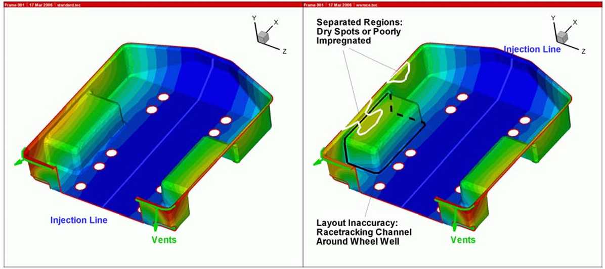
The effect of the race-tracking channel on resin flow in a one-piece automotive trailer is shown in Figure 1. The model predicts injection only for a particular case as dictated by the data provided in the flow simulation. How can a flow model be used to address the unknowns in the process and propose a process design that accounts for the variations expected on the shop floor, in the mold, and in the material to result in a void-free part? The modeling approach needs to be modified to focus on multiple scenarios that account for variations of the material and the process.
图1展示了竞流效应对一体式汽车拖车车厢成型过程中树脂流动的影响。该类仿真仅能够对流动模拟中输入的参数所确定的特定情况的注射过程进行预测。然而,该如何利用流动模型来解决工艺中的不确定性因素,并提出一种能够考虑到车间、模具和材料的预期变化,以实现无制造缺陷(如孔隙)的工艺设计?为此,当前的模拟方法还需要改进,以集中考虑材料和工艺流程的不确定性导致的不同情况。
LCM MODELING
The flow through porous media, such as fiber preforms, is usually described by Darcy’s law, that relates pressure gradient with flow velocity. The continuity (mass conservation) equation is used to obtain the governing elliptic partial differential equation for pressure [2]. The boundary conditions to apply are no flow through mold boundaries, prescribed pressure at flow front and prescribed pressure, flow rate or mixed boundary condition at the inlet and prescribed pressure (vacuum) at the moving flow-front. There are several algorithms available [2-7] to solve these equations.
LCM仿真
通过多孔介质(如纤维预成型体)的流动通常使用达西定律描述,该定律将压力梯度与流速联系起来。连续性(质量守恒)方程用来获取压力的椭圆偏微分控制方程[2]。所使用的边界条件为不可渗透边界,在注胶口处可以指定压力、流速或混合边界条件,在流动前沿指定压力(真空)边界。有几种算法可用于求解这些方程[2-7]。
Once the model is available, two issues must be addressed. First, it is necessary to determine whether and how the variability of process parameters may be included in the model. Second, one needs to establish algorithms that can execute the simulation with a range of parameters to determine a robust injection scheme which will produce a composite part without voids despite these variations.
一旦确定几何模型和控制方程,有两个问题必须解决:首先,有必要确定是否需要以及如何将工艺参数的离散性考虑在仿真中。第二,需要建立能够在一系列不同的参数下运行的模拟算法,以筛选出一个可靠的注射方案,保证工艺方案的容错性,使得在材料或工艺过程中可能出现的离散性范围内,也能生产出没有孔隙的复合材料部件。
The inclusion of variability in the model is straightforward. The material is described by its permeability K and fiber volume fraction vf. If these properties vary, variable properties may be assigned to the model. The "geometric" variability mentioned above does not imply different part shapes, but just the different preform accuracy along edges and bends. This is equivalent to local changes of permeability and may be handled as such, preferably with one-dimensional race-tracking channels [14].
将离散性纳入仿真模型是很直观的。材料由渗透率K和纤维体积分数vf两个参数描述。离散性导致的变化可以通过改变这两个参数来反映。前文所述的 "几何 "离散性并非指不同的构件形状,而是指预成型体边缘和拐角加工精度不同导致的几何形状的不同。这相当于渗透率的局部变化,仿真中可以考虑为一维流道(竞流效应)[14]。
MODELING THE VARIABLE PROCESS
模拟可变过程
Every simulation executed describes only one possible combination of material properties. To provide a robust injection scheme, one has to simulate multiple scenarios that represent the expected range of input values. If the process is automated, the computer can execute literally thousands of simulations. With manual execution, the number of cases is more limited, but in many cases it is possible to reduce or even eliminate creation of voids, with a selected number of judicious scenarios.
每一次模拟的执行过程都只能描述材料属性的一个可能组合。为了设计一个稳健的注射方案,模拟的材料属性组合必须覆盖全部预期的取值范围。如果这个过程是自动化的,计算机可以执行数以千计的模拟。在手动进行的情况下,案例的数量则比较有限。但在许多情况下,只需(通过适当的模拟分析后)选择一些明智的工艺方案,就有可能减少或甚至消除空洞的产生,。
Robust Injection Schemes
Most of VARTM-manufactured parts are essentially flat panels. To overcome restrictions on injection pressure, the sequential injection lines are introduced on the bagging side and opened when the flow arrives at that location. There are no sharp bends and, as the edges are sealed by the vacuum bag, racetracking-channels are less likely than in rigid molds. Flow is essentially one-dimensional, with the flow at the tool surface lagging behind that in the distribution media. Still, the variation of material parameters may jeopardize the injection, as premature opening of the next sequential line may create a dry spot behind this line (Figure 2, left).
稳健的注射方案
大多数VA-RTM制造的零件是类平板结构。为了克服注射压力的限制,在真空袋一侧可以设置连续的线注胶口,并在流动前锋到达该位置时打开。由于没有尖锐的弯曲角度,而且边缘使用真空袋密封,与刚性模具相比,这一工艺不常出现部件边缘的竞流效应。流动基本上是一维的,模具表面的流动滞后于导流网中的流动。然而,材料参数的变化可能会危及注射,因为下一个线注胶口的过早打开可能会在这个线后面产生一个干点(图2,左)。
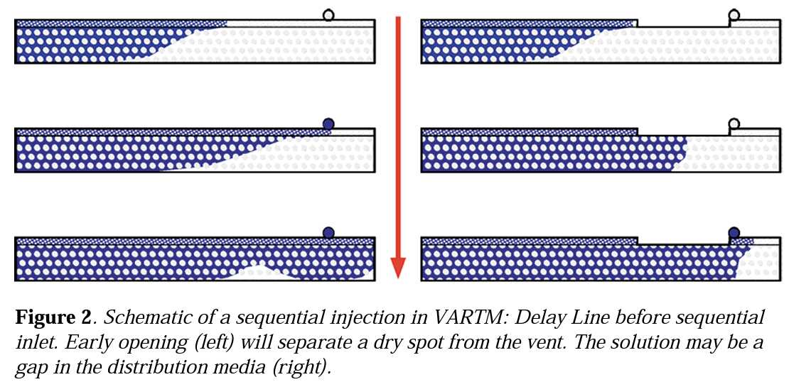
This issue may be addressed by providing a gap in distribution media (Figure 2, right). Under this gap, the flow front near the tool surface which was lagging behind catches up with the flow on the top and becomes one dimensional before the new injection line is opened,. This eliminates the possibility of entrapping a void in the part near the tooling surface. The gap should be as small as possible to avoid a large increase in the filling time but large enough to allow the flow to become one dimensional before the next injection line is opened.
这个问题可以通过在导流介质层设置一个间断来解决(如图2右侧所示)。当树脂到达导流介质的一端时,靠近模具表面(底面)的流动前沿将逐步追上顶面的流动前沿,并在新的注胶口打开之前形成一维(齐平的)流动前沿界面。这就消除了在模具表面附近的制品中产生空气包裹形成孔隙的可能。该导流介质的间断应尽可能小,以避免冲模时间的大幅增加,但也要足够大,以便在下一个注射线打开之前使流动前沿界面成为稳定的平面。
The success of this injection strategy depend on the values of the distribution media permeability and the in-plane and through-the-thickness permeability of the preform used in the simulation. These may vary greatly from one exeriment to the next. The modeling can overcome this issue by simulating the flow with the highest and lowest value of each of them and selecting a gap or delay size that can produce successful injection for all cases.
这种灌注策略的成功与否取决于模拟中使用的导流介质的渗透率以及预成型体的面内和厚度方向的渗透率数值(是否准确)。这些参数在通过实验获取时可能产生很大的离散。然而,通过模拟这些参数的最大值和最小值的组合是的流动形式,并选择一个能在所有情况下都可以确保灌注方案成功的导流介质的间隙是可行的。
Provision of Additional Resin Vents
The "Passive" Control: The traditional answer to varying material parameters and racetracking is creation of extra vents within the mold. The vents are closed during the injection when the resin arrives there, earning the the title of "passive" control [15]. Placement of the vents may be based on intuition, but the modeling capabilities allow one to approach the issue more scientifically and, above all, with better success rate.
设置冗余的树脂溢料口--"被动 "控制
对于不同的材料参数和流道,传统的解决方案是在模具内设置冗余的溢料口。在注射过程中,当树脂到达那里时关闭该溢料口。该方法被称为"被动 "控制[15]。 溢料口位置的选取可以基于经验,但仿真的使用能够让人们更科学地处理这个问题。更重要的是可能带来更高的成功率。
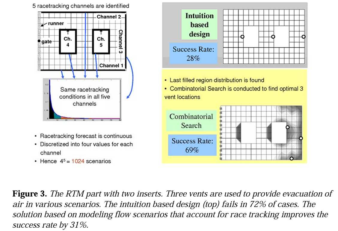
The variability in material parameters and racetracking may be included in the model. Discretizing the levels of race tracking strength, finite number of scenarios is generated. Probability levels may be associated with each scenario. Selecting the most likely vent location improves the odds considerably, as demonstrated in Figure 3 [15]. Note that if one adopts more number of vents, the resulting success rate will be higher.
材料参数的离散性和可能出现的边缘效应可以在仿真模型中考虑到。将边缘效应的强度分成几个等级,通过对这有限的几个等级进行分析,并将每个等级可能出现的概率水平相关联。如图3[15]所示,选择最可能的出胶口位置可以大大地提高灌注成功的概率。请注意,如果设置更多的冗余出胶口,成功率会更高。
Changing the Flow on the Fly
The "Active" Control: The passive control does not quite eliminate the potential for failure, it just dramatically reduces its likelihood. In some cases, the failure is not an option. Either the part is too large to waste or the continuity of the production might suffer too much. In that case, the active control comes to play. In actively controlled filling algorithm, the resin flow is monitored by imbedded sensors. Once the disturbance is detected, the system must determined what is happening and take a corrective measure, such as opening/closing injection ports or regulating the flow rate.
在线控制树脂流动 - "主动 "控制
被动控制并没有完全消除灌注失败的可能性,只是将其大大降低了。在某些情况下,这种灌注失败是不可接受的。比如是产品太大,报废成本极其高昂,或者生产的连续性不能中断。在这种情况下,主动控制能够发挥更好的作用。在主动控制的充模算法中,树脂的流动可以使用嵌入(在模具内)的传感器进行监控。一旦检测到不符合设计的流动形式,决策系统进行判断并采取预设的纠正措施,如打开/关闭注胶口或调节注胶速度。
The current state of the art in Liquid Molding does not allow one to provide detection in real time. Thus, just like in the case of passive control number of scenarios is prepared and modeled. Then, under software control a position of sensors is determined and detection database is prepared to determine the scenario from the sequencing of resin arrival at sensor locations. Optimization algorithm, through automated execution of filling simulations, determines the corrective measures needed to take place to steer the flow to desirable pattern (vent location).
目前,液体成型的技术水平还不允许人们进行实时的灌注过程监测。因此,就像在被动控制的情况下,需要准备和模拟多种情况(,从而形成数据库)。然后,在软件控制下确定传感器的位置,并准备检测数据库,以从树脂到达传感器位置的顺序中确定对应的情况。通过自动执行灌注模拟,优化算法确定所需的流动纠正措施,以引导流动形式符合理想的模式(即到达出气口位置)。
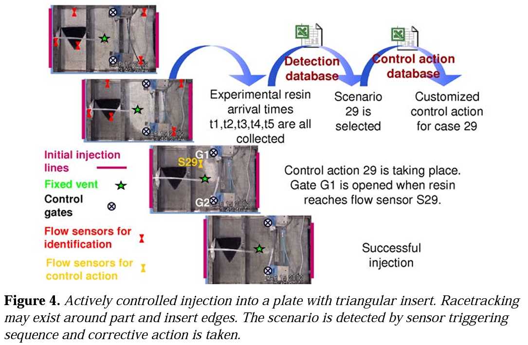
The actual action of active control is demonstrated in Figure 4 for the case of a flat panel with a triangular insert injected from line gates on both sides (Figure 4) with a vent in the middle. In this case, the scenarios included 2 different strengths of race tracking around the edges and the insert and the control action steers the flow towards the vent location.
图4展示了主动控制的实际动作,其案例是一块有着三角形嵌件的平板,平板两测各有一个线性注胶口(图4),中间设有排气口。在这种情况下,方案包括在平板侧边缘和嵌件周围的2种不同强度的竞流效应,控制动作将树脂的流动引导至目标出气口位置。
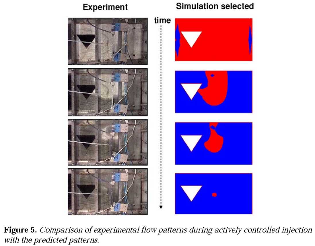
First, the resin triggers the installed sensors. From the order of sensor activation, the flow pattern and existing disturbance(s) are determined by lookup in pre-prepared database. For the case shown in Figure 4, it determines strong race tracking along the bottom edge of the part. The data base also offers the pre-determined corrective action which is triggered by another sensor input. Opening the auxiliary gate steers the resin flow towards the inlet and no void is formed. Figure 5 shows the comparison of experimental flow, captured through the acrylic mold top, and the simulation predictions made for the corrective action.
首先,树脂会触发已安装的传感器。根据传感器被触发的顺序,通过与已经准备好的数据库进行比对便可以确定(当前的)流动模式和存在的干扰因素。对于图4所示的案例,(主动控制系统检测到)沿部件底部边缘强烈的竞流效应。数据库还提供了预先确定的纠正措施,这由另一个传感器的输入来触发。打开辅助注胶口阀门将树脂引入,避免孔隙的形成。图5显示了通过丙烯酸树脂模具顶部捕捉到的触发主动控制系统进行流动修正时的实验实际流动形式和模拟预测的结果的比较。
Such verification is necessary in developing the flow control schemes. As all this is controlled with a computer, the operator does not have to reproduce his lay up for the next part. This approach to automated manufacturing in which the variations in the material handling and process is corrected with sensors and simulations will consistently improve the yield.
在开发灌注控制方案时,这种验证是必要的。由于所有这些都是由计算机控制的,操作人员不必为保证下一个结构件也严格按照相同的铺层方式而烦恼。这种采用自动化制造的方法,通过传感器和模拟来纠正材料处理和工艺过程中产生的材料离散性(对灌注过程产生的影响),能够不断的提高产量。
CONCLUSIONS AND FUTURE OUTLOOK
The resin injection in LCM process is not entirely repeatable because of (a) the variability in material parameters and (b) the geometrical inaccuracy of preform preparation an lay up. The existing simulation capabilities allow one to include both these effects. Thus, the simulation user can determine in advance the flow pattern during injection under various scenarios and design a robust injection scheme to achieve successful mold filling in most if not all scenarios.
结论和未来展望
LCM工艺中的树脂注射过程并不是完全可重复的,这是(a)材料参数的可变性和(b)预成型体制备和铺设过程中的几何误差导致的。现有的模拟能力允许人们将这两种因素考虑在内。因此,人们可以通过模拟事先确定各种情况下的注胶流动模式,从而设计一个容错性强的注胶方案,以便在大多数情况下(如果不是所有情况下)成功实现模具的无缺陷填充。
In many cases, risk reduction benefits may be reaped even by manually executing the simulation for several values of material parameters, usually by executing the simulation for the lowest and highest possible values. However, to fully harness the simulation capabilities, one must address the material variability and introduce coupling of process modeling with optimization programs because of the large number of permutations involved.
在许多情况下,即使手动运行几个材料参数组合的模拟,也能明显降低注射方案的风险。这种情况下通常是对材料参参数可能取到的最低和最高值进行模拟。然而,针对不同参数的模拟是对大量参数的排列组合逐一试错的过程,为了充分利用模拟能力,解决材料的可变性问题,必须将工艺模拟与过程优化结合起来。
Designing a simple passive control approach, such as providing a couple of extra vents, is relatively straightforward and greatly reduces the risk of injection failure. Active control is more involved, but allows one to design risk-free injection scenarios even with variable material and preforming. In order to design an active control, additional software tools are needed to determine sensor locations and design the control action.
设计一些被动控制方案,如备用排气口,是相对简单的,并且可以大大降低注射失败的风险。主动控制涉及的内容更多,但允许人们即使是在材料和预成型体不同时也能够设计出无风险的注射方案。但是,为了设计一个主动控制系统,需要额外的软件来确定传感器的位置和设计控制动作。
These software tools depend on repetitive execution of process simulation to accomplish their goal. The future role of simulations in addition to predictive modeling and a design tool will be to integrate with conceptual design and with a controls system on the shop floor to improve the yield and reduce the time for prototype development as shown in figure 6.
这些软件依赖于重复执行工艺模拟来实现其目标。如图6所示,除了预测模型和设计工具之外,模拟的未来角色将是与概念设计和车间的控制系统相结合,以提高产量,减少原型开发的时间。
Comments NOTHING