[TOC]
Gmsh 操作指南—GUI操作
**1. 几何区域构建 **
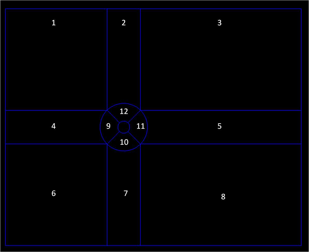
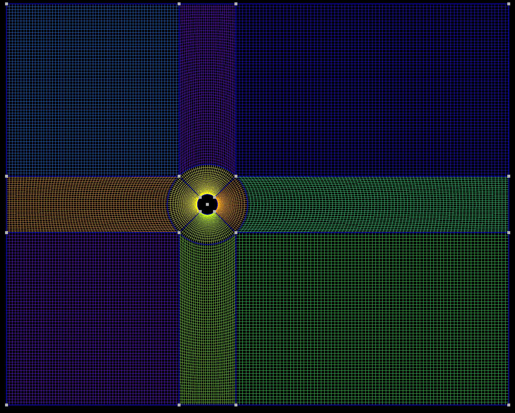
要构建的几何体如下图所示:
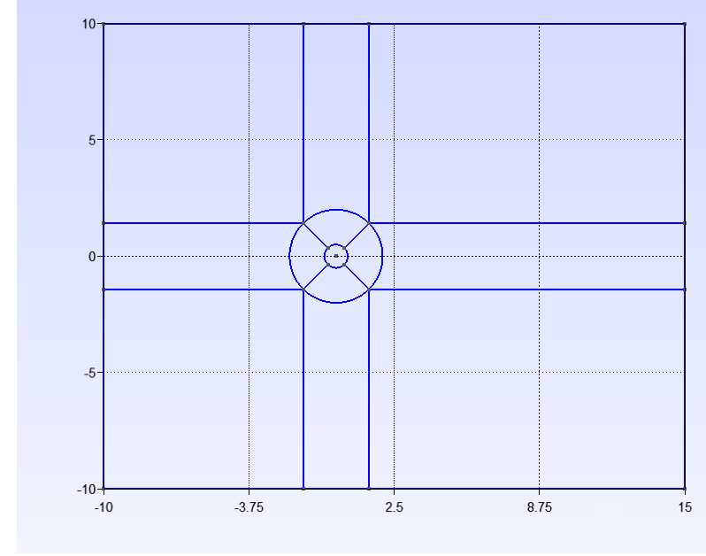
从图中可以看到计算域被划分成12块,其中圆柱周围划分了四块扇形区域,这个区域可以做拉伸网格,让网格由外到内逐渐加密。其余部分在没有其他特殊需求下,可以直接使用均匀网格。
- File-> New -> 输入文件名"cylinder"-> 默认使用 OpenCASCADE 几何核心
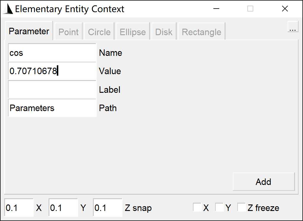
- 新建参数:Modules->Geometry->Elementary entities->Add->Parameter 添加参数 d 与 cos
d=diameter=1
cos=cos45=0.70710678
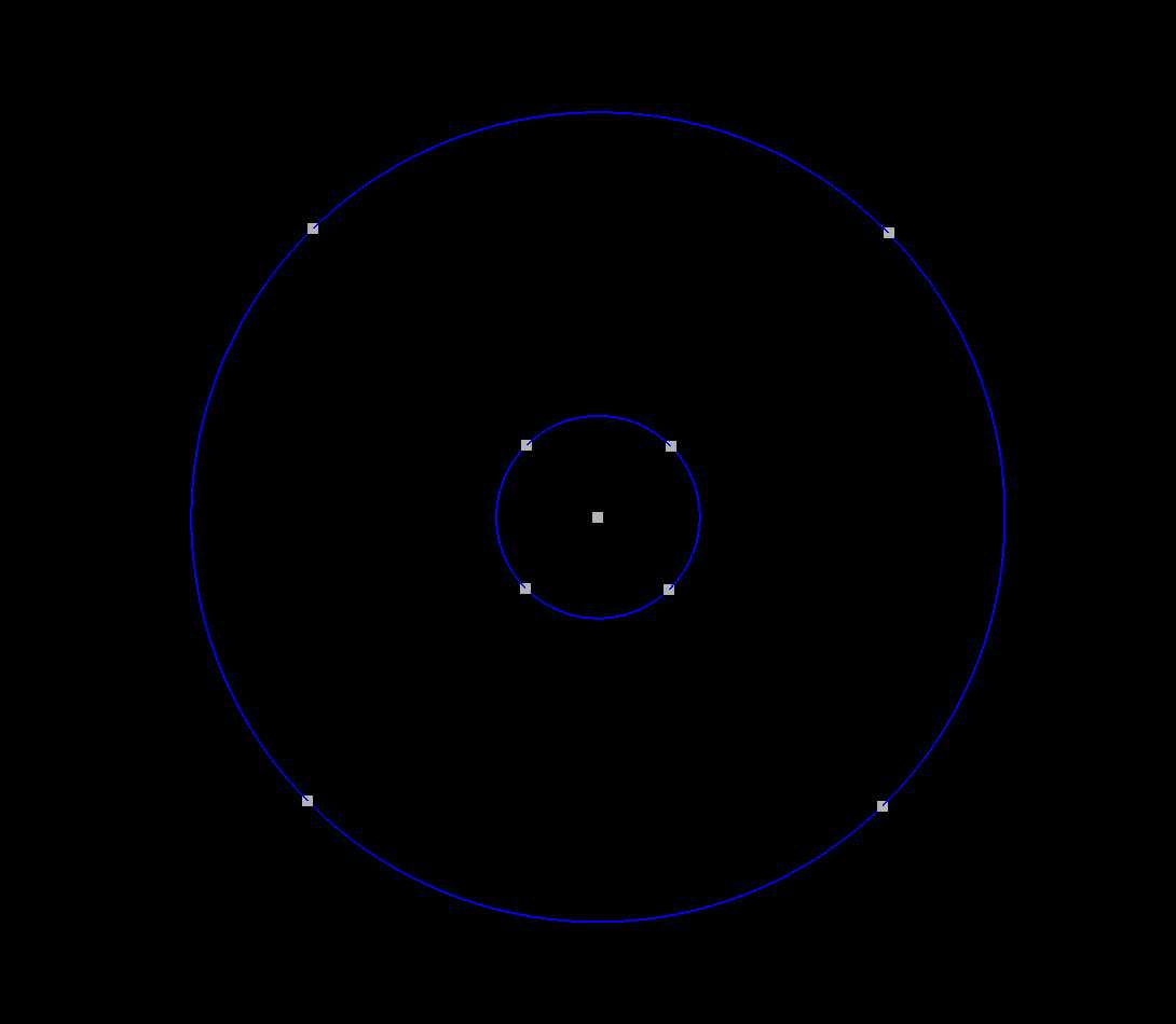
- 添加点: Modules->Geometry->Elementary entities->Add->Point, 添加点(0,0,0), 并依次添加点
Point(2) = {d/2*cos, d/2*cos, 0, 1.0};
Point(3) = {-d/2*cos, d/2*cos, 0, 1.0};
Point(4) = {-d/2*cos, -d/2*cos, 0, 1.0};
Point(5) = {d/2*cos, -d/2*cos, 0, 1.0};

Point(6) = {2*d*cos, 2*d*cos, 0, 1.0};
Point(7) = {-2*d*cos, 2*d*cos, 0, 1.0};
Point(8) = {-2*d*cos, -2*d*cos, 0, 1.0};
Point(9) = {2*d*cos, -2*d*cos, 0, 1.0};

Point(10)={-10*d, -10*d,  0,  1.0};
Point(11)={-10*d, 10*d,  0,  1.0};
Point(12)={15*d, 10*d,  0,  1.0};
Point(13)={15*d, -10*d,  0,  1.0};

Point(14) = {2*d*cos, 10*d, 0, 1.0};
Point(15) = {-2*d*cos, 10*d, 0, 1.0};
Point(16)= {-2*d*cos, -10*d, 0, 1.0};
Point(17) = {2*d*cos, -10*d, 0, 1.0};

Point(18)={-10*d, -2*d*cos,  0,  1.0};
Point(19)={-10*d, 2*d*cos,  0,  1.0};
Point(20)={15*d, 2*d*cos,  0,  1.0};
Point(21)={15*d, -2*d*cos,  0,  1.0};
方法2:通过:Modules->Geometry->Edit script 编辑脚本添加上述点,保存脚本(此方法操作更加方便)
// Gmsh project created on Tue Jun 20 11:24:34 2023
SetFactory("OpenCASCADE");
//+
d = DefineNumber[ 1, Name "Parameters/d" ];
//+
cos = DefineNumber[ 0.70710678, Name "Parameters/cos" ];
//+
Point(1) = {0, 0, 0, 1.0};
Point(2) = {0.353553339, 0.35355339, 0, 1.0};
Point(3) = {-0.353553339, 0.35355339, 0, 1.0};
Point(4) = {-0.353553339, -0.35355339, 0, 1.0};
Point(5) = {0.353553339, -0.35355339, 0, 1.0};

Point(6) = {1.41421356, 1.41421356, 0, 1.0};
Point(7) = {-1.41421356, 1.41421356, 0, 1.0};
Point(8) = {-1.41421356, -1.41421356, 0, 1.0};
Point(9) = {1.41421356, -1.41421356, 0, 1.0};

Point(10) = {-10, -10, 0, 1.0};
Point(11) = {-10, 10, 0, 1.0};
Point(12) = {15, 10, 0, 1.0};
Point(13) = {15, -10, 0, 1.0};

Point(14) = {1.41421356, 10, 0, 1.0};
Point(15) = {-1.41421356, 10, 0, 1.0};
Point(16) = {-1.41421356, -10, 0, 1.0};
Point(17) = {1.41421356, -10, 0, 1.0};

Point(18) = {-10, -1.41421356, 0, 1.0};
Point(19) = {-10, 1.41421356, 0, 1.0};
Point(20) = {15, 1.41421356, 0, 1.0};
Point(21) = {15, -1.41421356, 0, 1.0};
通过Modules->Geometry->Reload script重新加载脚本。
- 连接曲线:Modules->Geometry->Elementary entities->Add->Circle arc
依次选择:圆弧->圆心->圆弧终点
- 连接直线::Modules->Geometry->Elementary entities->Add->Line
注意:平行方向的线尽量保证矢量方向一致,主要是方便做拉伸网格。
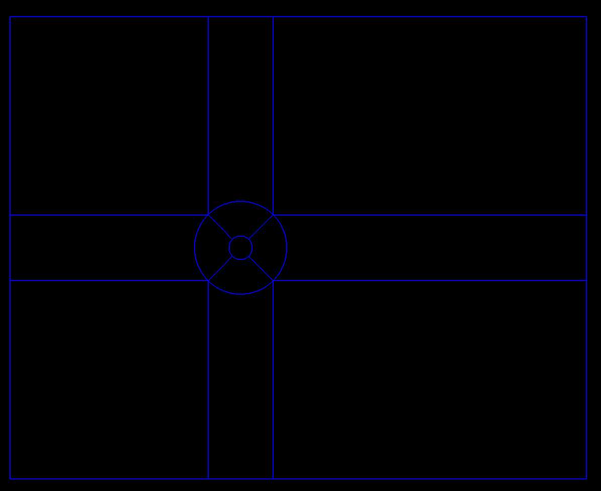
- 构建平面:Modules->Geometry->Elementary entities->Add->Plane surface 顺时针选取每一区域的四条边,构成平面。顺时针选取保证面的方向一致。
2. 二维网格生成
- Recombine: Modules->Mesh->Define->Recombine
选取步骤 6 中建立的所以平面
Recombine 的主要目的是为了尽可能地使用方形网格,Gmsh 默认是三角网格。
- 对线进行网格划分:定义每条线的网格划分数量,用来控制网格质量。Modules->Mesh->Define->Transfinite->Curve
如下图设置网格质量
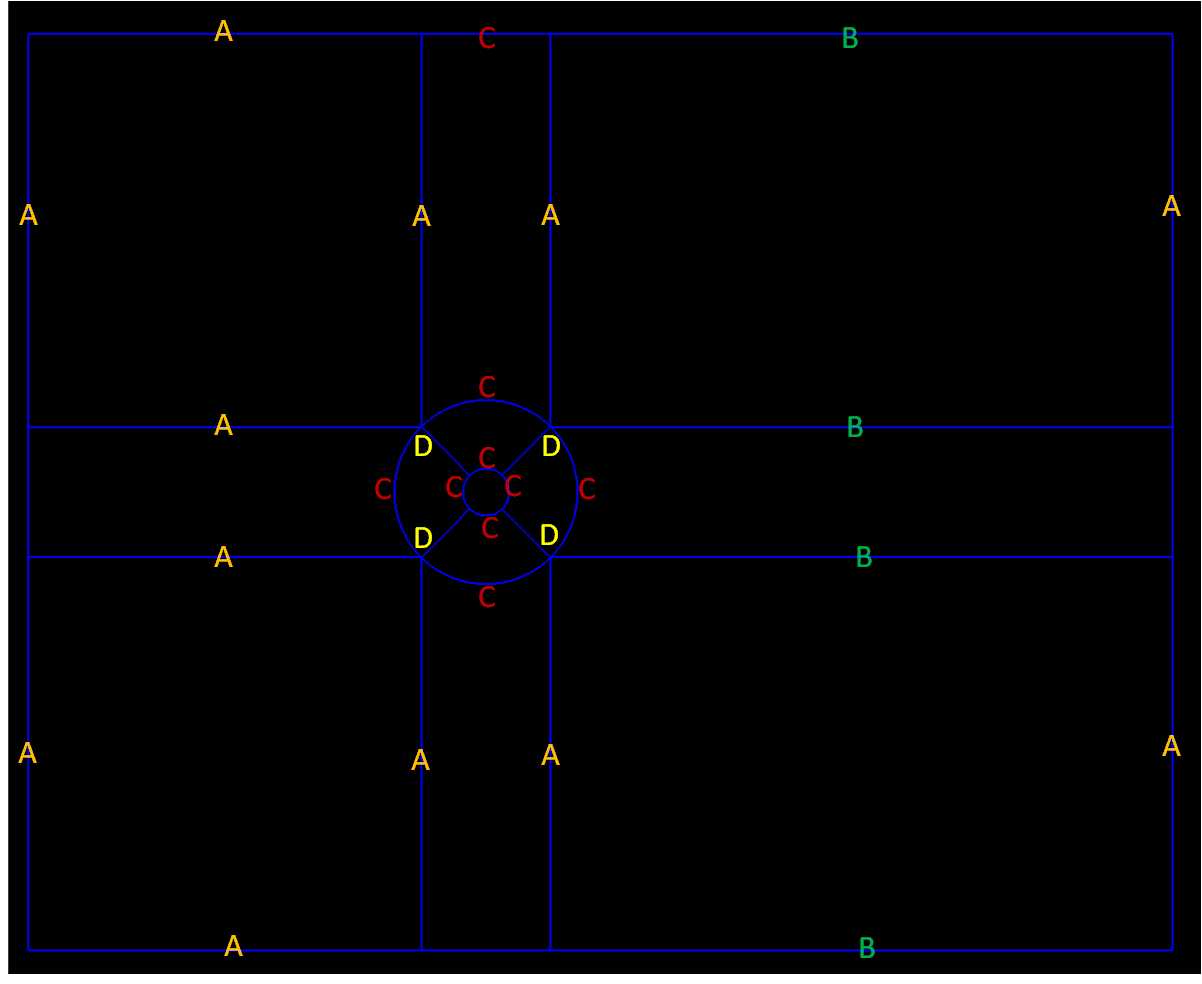
- A 组:61 number of points, Progression Type, 1 parameter, (均匀)
- B 组:81 number of points, Progression Type, 1 parameter, (均匀)
- C 组:31 number of points, Progression Type, 1 parameter, (均匀)
- D 组:31 number of points, Progression Type, 0.9 parameter, (非均匀) 跟直线方向定义有关,如果网格加密方向相反,参数改为 1.1
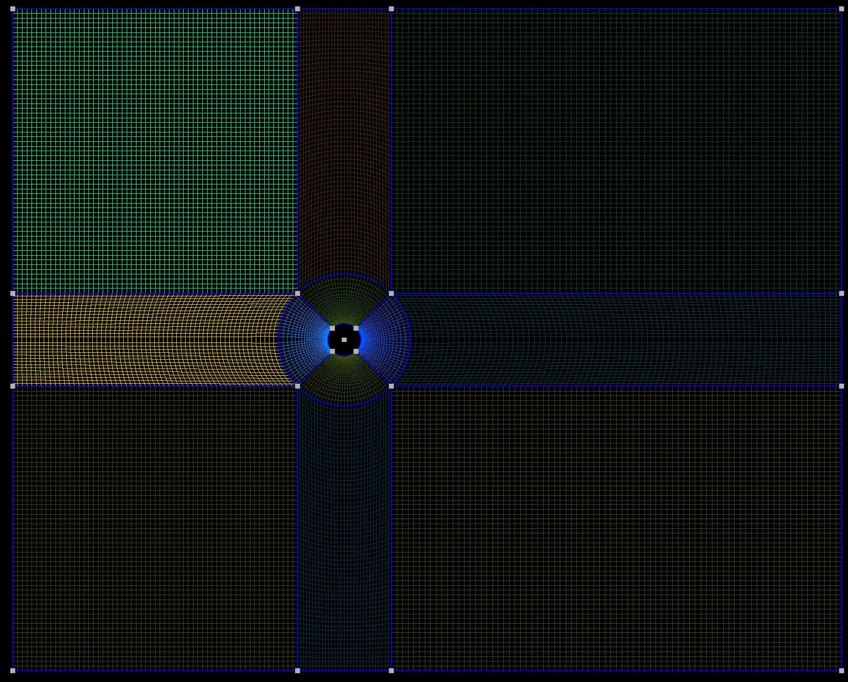
- 对面进行网格划分:Modules->Mesh->Define->Transfinite->surfaces 依次选取所有面
- 选择 Modules->Mesh->2D 生成网格,进行检查。
通过修改Script中的
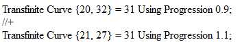
改变D组曲线的取向方向。
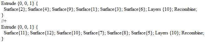
- 拉伸面,将其从二维变成三维。(因为 OpenFoam 的二维求解在第三个方向上至少需要一层网格) Modules->Geometry->Elementary entities->Extrude->Translate
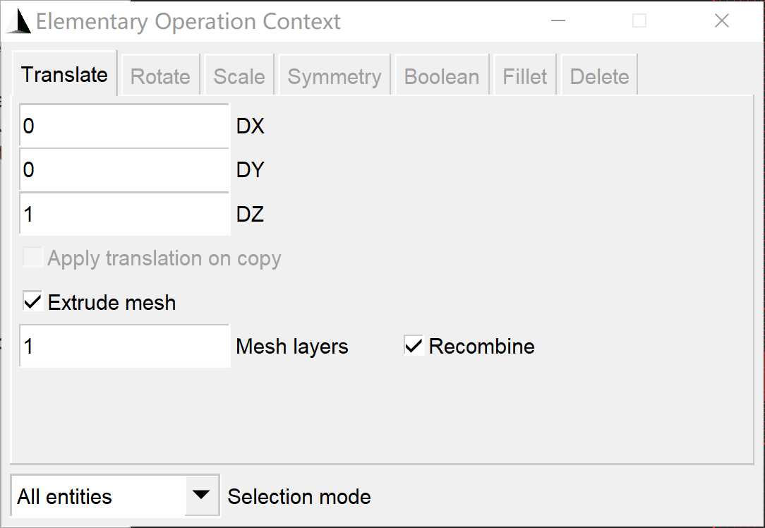
- 将Mesh layers 改为想要的数量,或者直接编辑脚本,可以改变层间厚度的网格层数
3. 几何面的分组标记
为了方便在有限元软件中设置边界条件和载荷,可以对几何进行分组
- 点击 Modules->Mesh->1D 恢复线框图
- Modules->Geometry->Physical group->Add->Point/ Curve/ Surface/ Volume
4. 保存网格
- 再次生成三维网格
- 点击 Modules->Mesh->3D
- File->Export
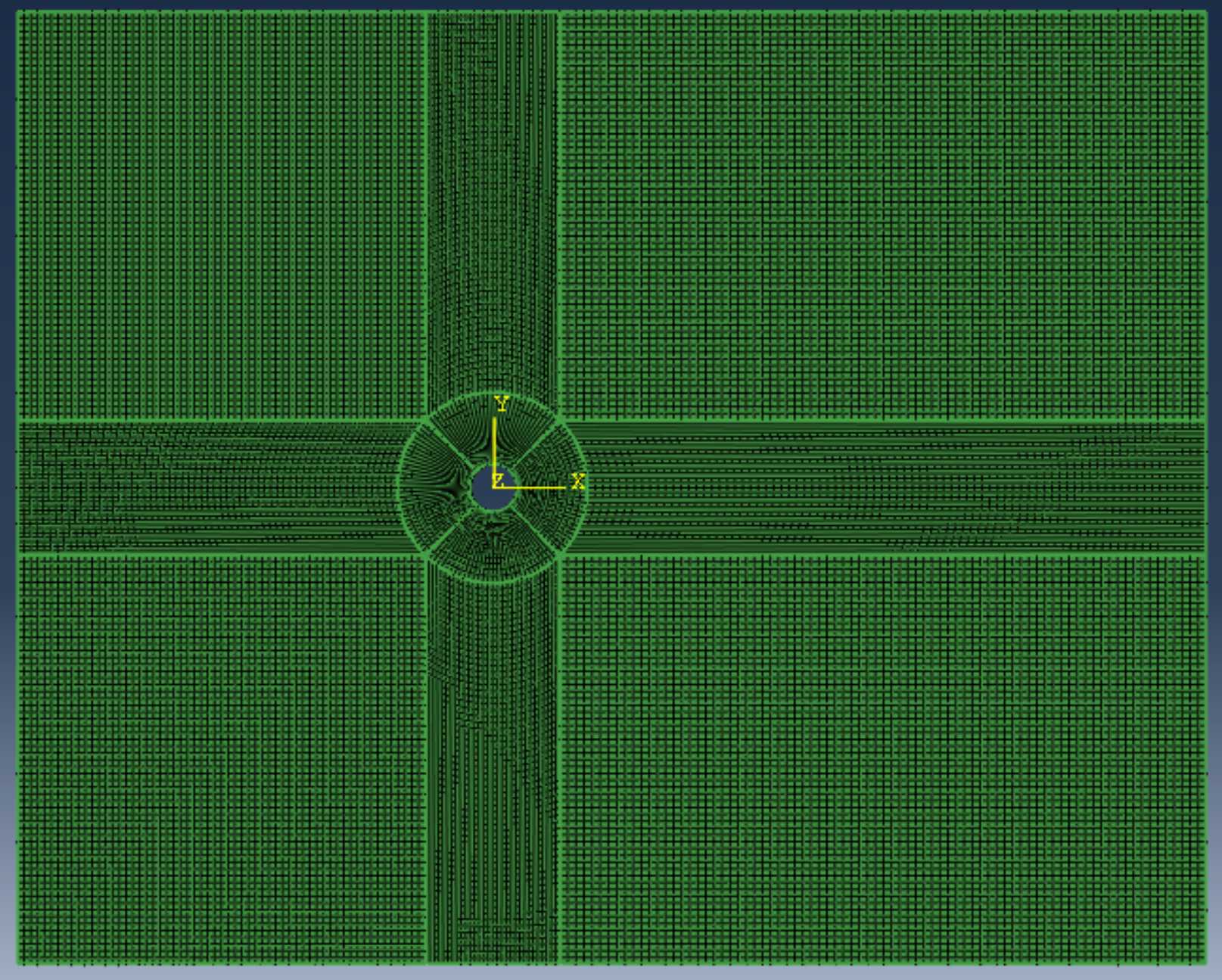
导出inp文件,并在Abaqus中打开:
Comments NOTHING